
How to Read a Schematic, Understanding of Graphical Symbols Used in Fluid Power Drawings
We all understand the basic components and functions of a fluid power unit. We also know its purpose is to use pressurized fluids in order to generate, control or transmit power. The flow and operation of each unit can vary depending on the specifications and requirements. However, when analyzing and understanding these power units, engineers craft up fluid power drawings. These detailed diagrams incorporate standard-based graphic symbols that depict the complete operation and fluid flow within the power unit. Each unit is divided up into five basic parts:
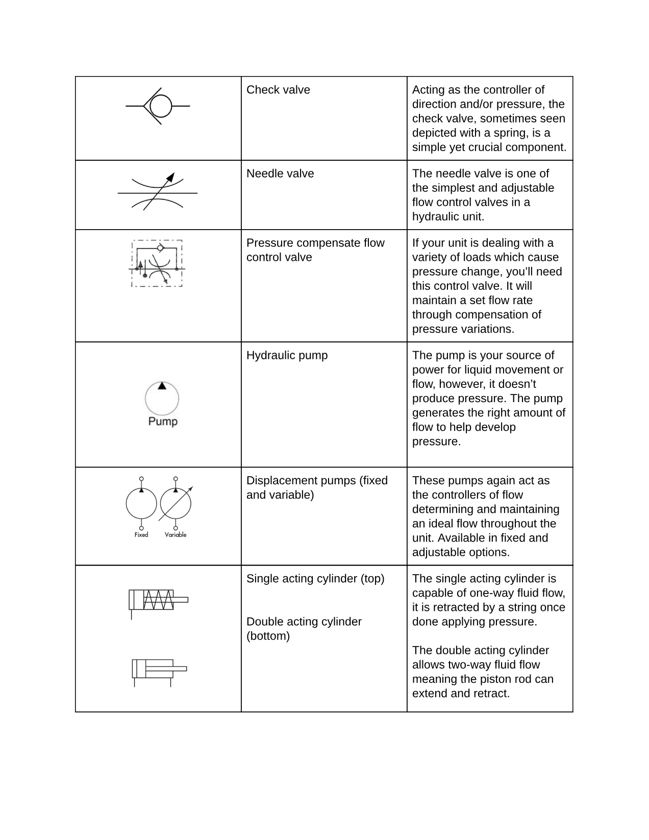
- Pumps
- Reservoirs
- Actuators
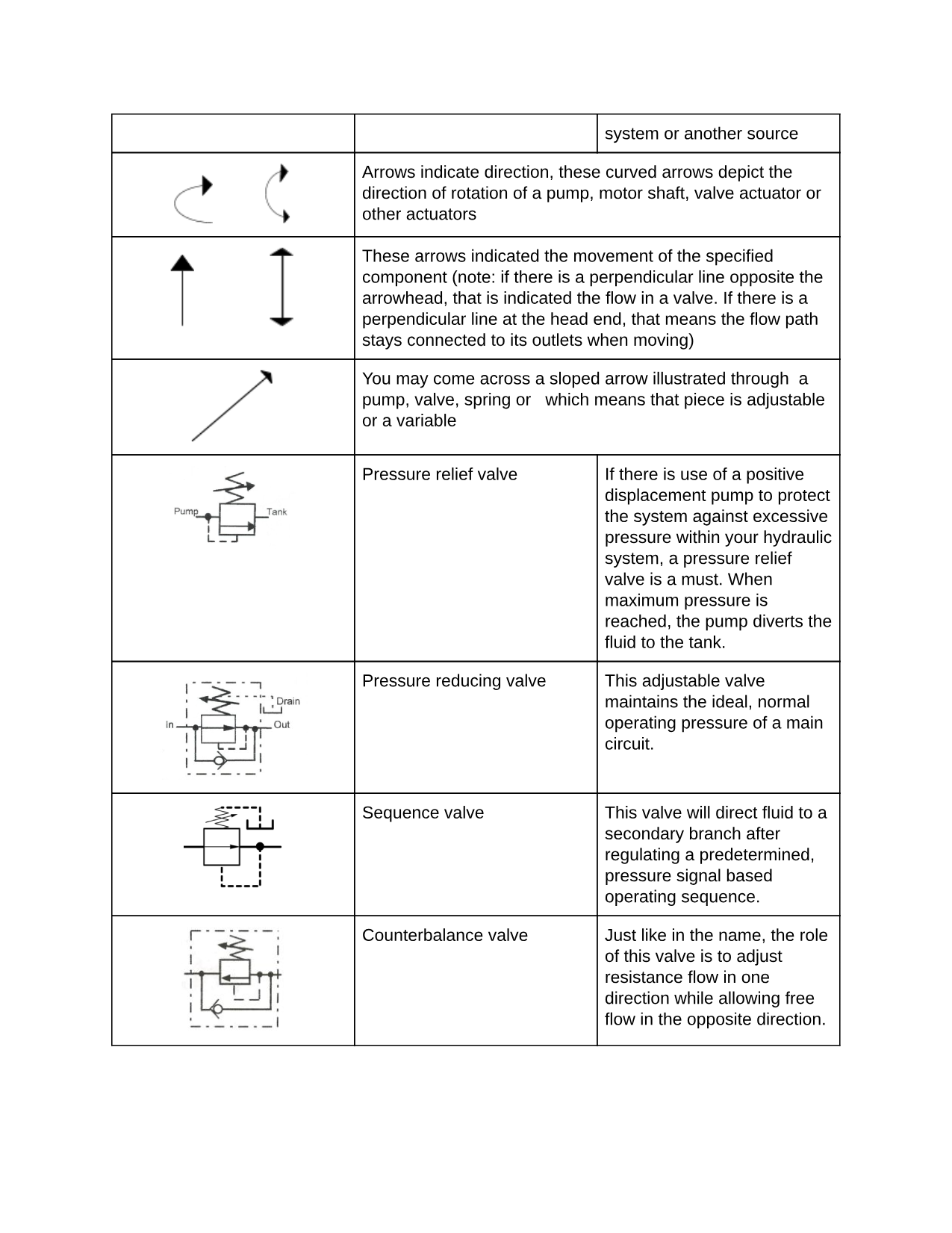
- Valves
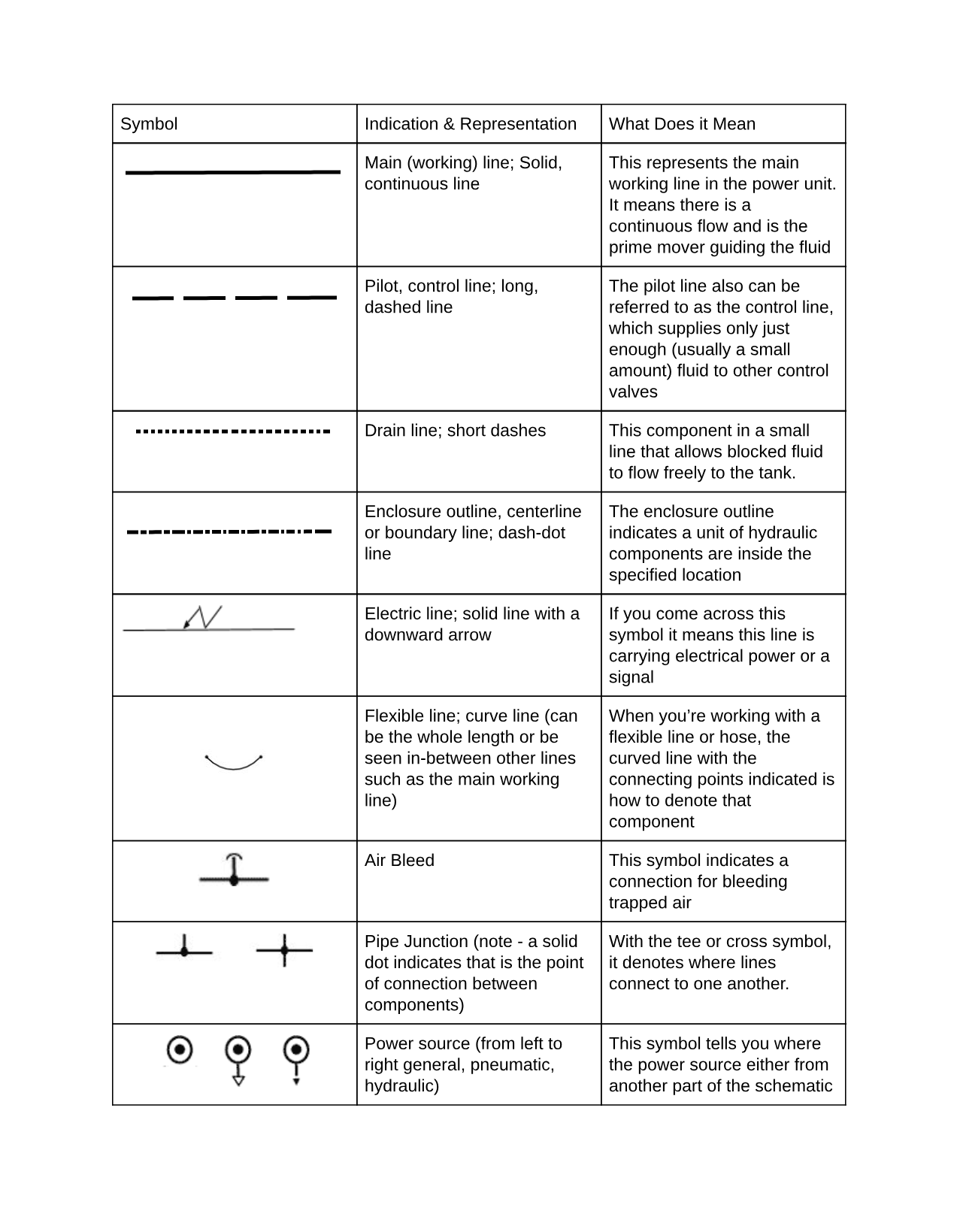
- Lines
Now although that is the universal makeup, the variations can be extreme and that is why it’s crucial to document each detail correctly and remain consistent across the board. The experts in this industry have agreed and contracted specified symbols in order to maintain that consistency, as well as, create a solid foundation for educational and industrial purposes. The design, fabrication, analysis, and services of fluid power units and circuits needed to be simplified and universal. These drawings also help ease communication between any business parties in the hydraulic power industry, no matter what their mother-language is. These symbol standards have opened global networking, partnership opportunities and have created a more efficient documentation system for fluid power units.
Fluid Power Drawing Symbols: Rules to Remember
There are a few vital points to note when designing a fluid power drawing with graphics and industry symbols. As mentioned, the variety is vast when it comes to these engineered drawings and some companies will still have their own particular nuances. For the majority, however, each hydraulic expert knows these key components:
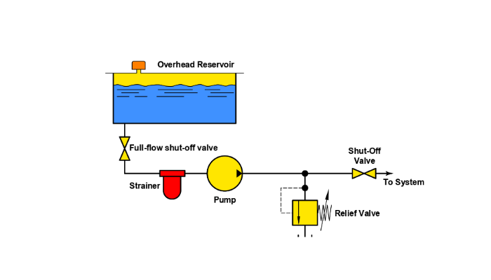
- Show connection, paths, and functions of hydraulic components
These drawings are meticulous in nature but really just scratch the surface of operational specifications within the depicted power unit. These symbols represent the overall flow path and transition points.
- Does not express construction or value
When reading these fluid power graphics you’ll notice component settings such as pressure and flow rate are not indicated or verified. Other missing pieces may be symbols indicated for the location of ports, a specified direction of shifting spools or certain actuator details.
- Use symbols in combination to express details or certain specifications
In order to show certain functions, a combination of symbols must be applied. This should also be practiced if you come across a certain component or function that may not have a designated symbol yet. By following the basic outlines companies are able to create unique symbols, if necessary, that still meet the industry standards.
How to Read and Understand Fluid Power Graphic Symbols
Now that the overall purpose, foundation, and limitations of the standardized fluid power symbols has been established, let’s look into the details of the various symbols. The drawings can be broken down by the five foundation components of a hydraulic power unit. From there the symbols will fluctuate through different variations which point to factors like, the direction of the hydraulic pump or motor shaft.
We have illustrated the basic fundamentals of the reading and understanding of these graphical symbols used in fluid power drawings. We have mapped out the primary basis of symbols, including hydraulic components such as valves. As aforementioned these symbols can be used in combination to depict more complex components of the fluid power unit.
Air and Hydraulic Equipment in Middle Tennessee
If you need any further schematic information or have other power unit questions our team of hydraulic experts is located throughout Middle Tennessee. We can help you find the right component, the proper filtration system and even repair your existing power unit on site. Contact us today for all of your fluid power needs!


